

How to Properly Install a 1500VDC 30A 10×85mm Solar PV DIN Rail Fuse Holder in a Combiner Box
2026-06-09
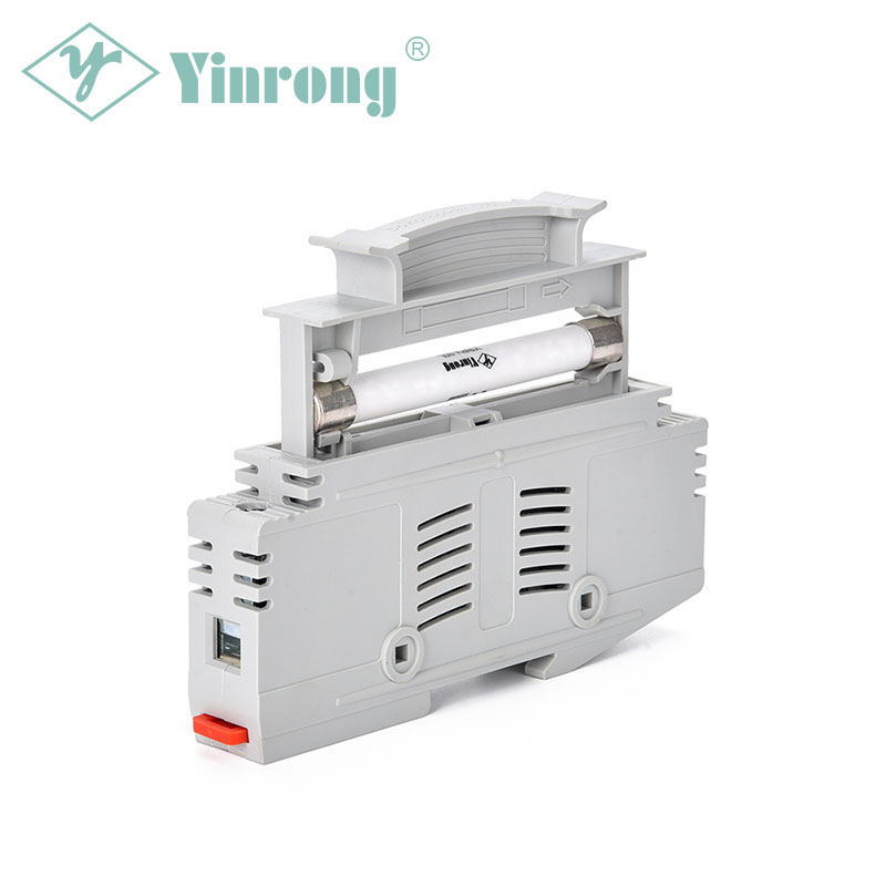
Installing a 1500VDC 30A 10×85mm Solar PV DIN Rail Fuse Holder from Galaxy Fuse inside a PV combiner box requires careful attention to voltage ratings, torque specifications, and clearance distances. Unlike lower-voltage holders, this 1500VDC component demands stricter arc protection and insulated DIN rail mounting.
Tools and Pre-Installation Checklist
| Item | Specification / Action |
|---|---|
| DIN rail | 35mm steel or insulated type |
| Torque driver | 2.5–3.5 Nm (per Galaxy Fuse datasheet) |
| Fuse type | 10×85mm gPV or aR, 30A rating |
| Wire gauge | 10–16 mm², PV-certified, 1500VDC insulation |
| PPE | Arc-rated gloves and face shield |
Step-by-Step Installation
-
De-energize the combiner box and verify zero voltage.
-
Mount the DIN rail securely. Slide the 1500VDC 30A 10×85mm Solar PV DIN Rail Fuse Holder onto the rail until it clicks.
-
Insert the Galaxy Fuse 10×85mm fuse into the holder. Confirm the 30A marking faces outward.
-
Strip wires to 12 mm. Connect PV+ input to the line side; PV+ output (to inverter) to the load side.
-
Tighten terminals to specified torque. Loose connections cause overheating in 1500VDC systems.
-
Label the holder clearly: “1500VDC 30A 10×85mm – Galaxy Fuse”.
Common Installation Errors to Avoid
| Error | Consequence |
|---|---|
| Using aluminum wire | Terminal corrosion |
| Skipping arc chute inspection | Reduced breaking capacity |
| Mixing 10×38mm fuses | Overheating and false trips |
1500VDC 30A 10×85mm Solar PV DIN Rail Fuse Holder FAQ
Q: Can I replace a 1000VDC holder with this Galaxy Fuse 1500VDC model without changing the combiner box?
A: Yes, provided the combiner box has a minimum 1500VDC creepage distance (usually >25 mm) and the DIN rail is rated for 1500VDC. The 10×85mm footprint is identical to many 1000VDC holders, but always check the box’s nameplate. Galaxy Fuse recommends verifying insulation voltage before retrofitting.
Q: What is the correct torque for the Galaxy Fuse 1500VDC 30A 10×85mm Solar PV DIN Rail Fuse Holder?
A: The specified torque range is 2.8–3.2 Nm for copper wire (10–16 mm²). Over-tightening can crack the holder base; under-tightening increases contact resistance, leading to thermal runaway at 30A continuous current. Galaxy Fuse includes a torque label on the holder body for field reference.
Q: How do I test the holder after installation without damaging the fuse?
A: Remove the fuse first. Then measure continuity from line to load terminals – it must be open. Insert the fuse and measure again: resistance should be <0.5 mΩ. Use a DC insulation tester at 2000VDC to check between terminals and ground. Galaxy Fuse advises never testing through the fuse with a high-current meter.
Need Technical Support?
For system design validation or bulk order assistance with the 1500VDC 30A 10×85mm Solar PV DIN Rail Fuse Holder, the Galaxy Fuse engineering team provides free arc-flash analysis and DIN rail layout reviews. Contact us today with your combiner box schematic – our certified PV specialists respond within 24 hours.